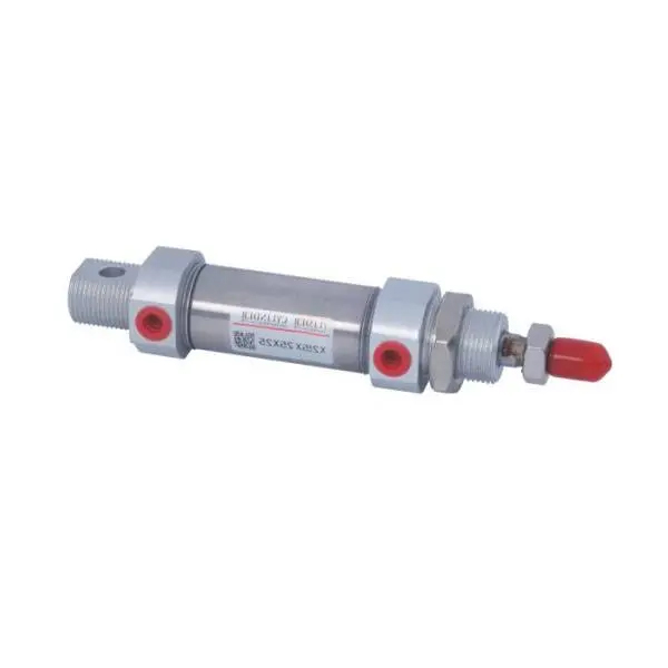
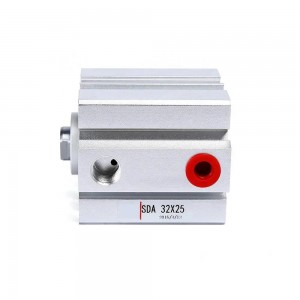
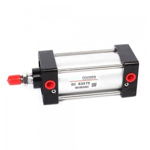
C85 Series aluminum alloy acting pneumatic European standard air cylinder
Product Description
The design of the cylinder has been carefully optimized, using a reliable sealing system and wear-resistant materials to ensure long-term reliable operation. It also has an adjustable buffer device that can reduce impact force and extend the service life of the cylinder.
The C85 series cylinders have multiple installation and connection methods and can be used in conjunction with various pneumatic equipment and control systems. It can also be customized according to the specific requirements of customers to meet the needs of different application scenarios.
Technical Specification
|
Bore Size(mm) |
8 |
10 |
12 |
16 |
20 |
25 |
|
Acting Mode |
Double acting |
|||||
|
Working Media |
Cleaned Air |
|||||
|
Working Pressure |
0.1~0.9Mpa(1~9kgf/cm²) |
|||||
|
Proof Pressure |
1.35Mpa(13.5kgf/cm²) |
|||||
|
Working Temperature |
-5~70℃ |
|||||
|
Buffering Mode |
Rubber Cushion / Air Buffering |
|||||
|
Port Size |
M5 |
1/8 |
||||
|
Body Material |
Stainless Steel |
|||||
Stroke Of Cylinder
|
Bore Size (mm) |
Standard Stroke(mm) |
Max.stroke (mm) |
Allowable stroke(mm) |
|
8 |
10 25 40 50 80 100 |
300 |
500 |
|
10 |
10 25 40 50 80 100 |
300 |
500 |
|
12 |
10 25 40 50 80 100 125 150 175 200 |
300 |
500 |
|
16 |
10 25 40 50 80 100 125 150 175 200 |
300 |
500 |
|
20 |
10 25 40 50 80 100 125 150 175 200 250 300 |
500 |
1000 |
|
25 |
10 25 40 50 80 100 125 150 175 200 250 300 |
500 |
1000 |
Selection Of Sensor Switch
|
Mode/Bore Size |
8 |
10 |
12 |
16 |
20 |
25 |
|
Sensor Switch |
CS1-F CS1-U D-Z73 CS1-S |
|||||
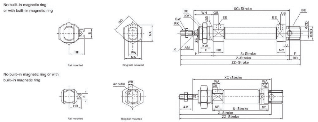
|
Bore Size(mm) |
AM |
BE |
φC |
φDC |
φD |
EW |
F |
EE |
GB |
GC |
WA |
WB |
H |
HR |
K |
KK |
|
8 |
12 |
M12X1.25 |
4 |
4 |
17 |
8 |
12 |
M5X0.8 |
7 |
5 |
|
|
28 |
10 |
|
M4X0.7 |
|
10 |
12 |
M12X1.25 |
4 |
4 |
17 |
8 |
12 |
M5X0.8 |
7 |
5 |
|
|
28 |
10.5 |
|
M4X0.7 |
|
12 |
16 |
M16X1.5 |
6 |
6 |
20 |
12 |
17 |
M5X0.8 |
8 |
6 |
|
|
38 |
14 |
5 |
M6X1 |
|
16 |
16 |
M16X1.5 |
6 |
6 |
20 |
12 |
17 |
M5X0.8 |
8(5.5) |
6(5.5) |
9.5 |
6.5 |
38 |
14 |
5 |
M6X1 |
|
20 |
20 |
M22X1.5 |
8 |
8 |
28 |
16 |
20 |
G1/8 |
8 |
8 |
11 |
9 |
44 |
17 |
6 |
M8X1.25 |
|
25 |
22 |
M22X1.5 |
10 |
8 |
33.5 |
16 |
22 |
G1/8 |
8 |
8 |
11 |
10 |
50 |
20 |
8 |
M10X1.25 |
|
Bore Size(mm) |
KV |
KW |
NB |
NC |
NA |
φND |
RR |
S |
SW |
U |
WH |
XC |
Z |
ZZ |
|
8 |
17 |
7 |
11.5 |
9.5 |
15 |
12 |
10 |
46 |
7 |
6 |
16 |
64 |
76 |
86 |
|
10 |
17 |
7 |
11.5 |
9.5 |
15 |
12 |
10 |
46 |
7 |
6 |
16 |
64 |
76 |
86 |
|
12 |
22 |
6 |
12.5 |
10.5 |
18 |
16 |
14 |
50 |
10 |
9 |
22 |
75 |
91 |
105 |
|
16 |
22 |
6 |
12.5(12.5) |
10.5(12.5) |
18 |
16 |
13 |
56 |
10 |
9 |
22 |
82 |
98 |
111 |
|
20 |
30 |
7 |
15 |
15 |
24 |
22 |
11 |
62 |
14 |
12 |
24 |
95 |
115 |
126 |
|
25 |
30 |
7 |
15 |
15 |
30 |
22 |
11 |
65 |
17 |
12 |
28 |
104 |
126 |
137 |
